
EDWARDS
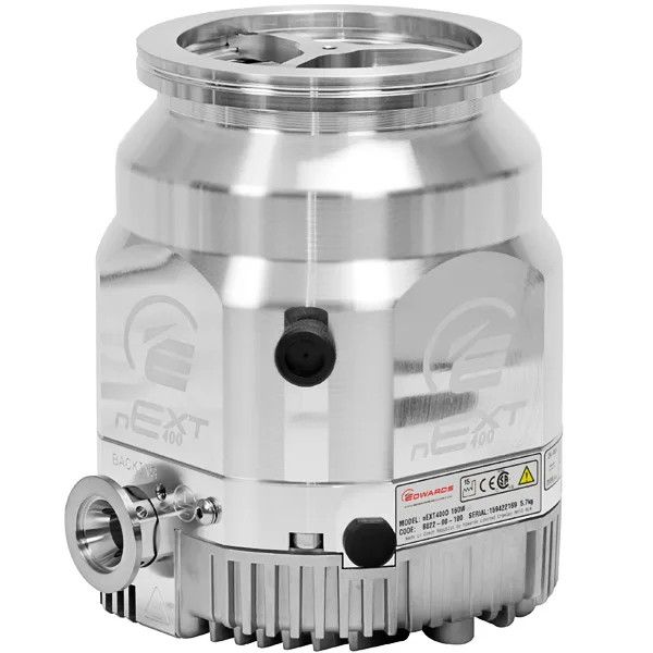
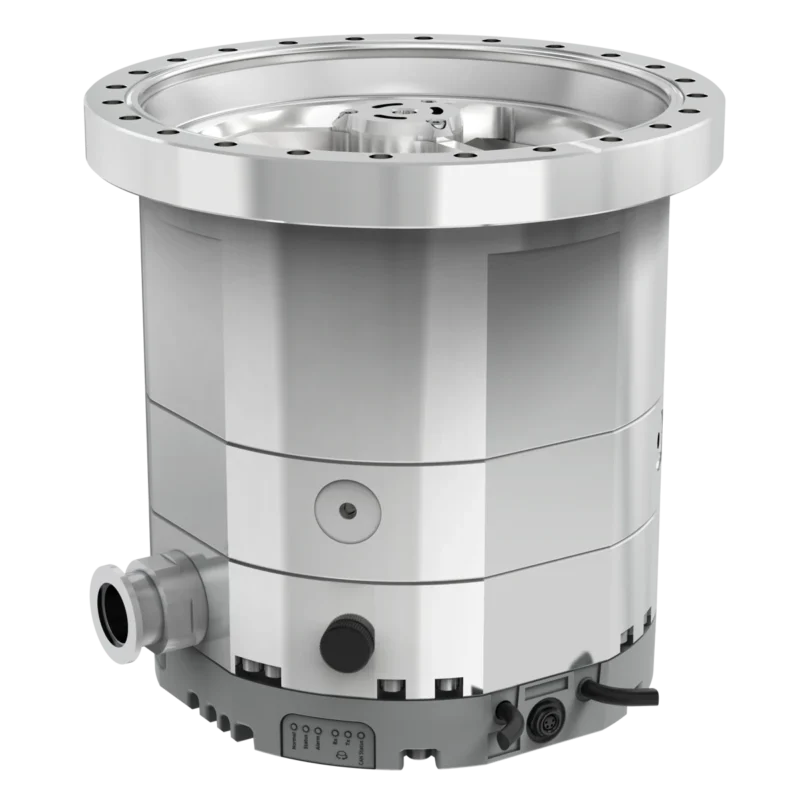
Edwards nEXT400D Turbomolecular Vacuum Pump
- Pumping speed — nitrogen
- 400 l/s
- High-vacuum inlet connection
- DN160 ISO-K or CF
- Cooling
- Air and water cooling accessories available; select for the gas load and ambient conditions

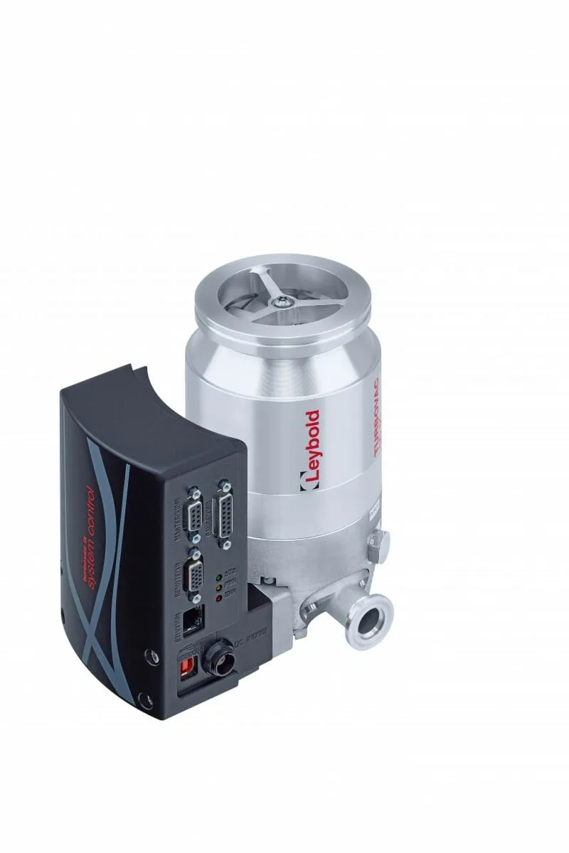
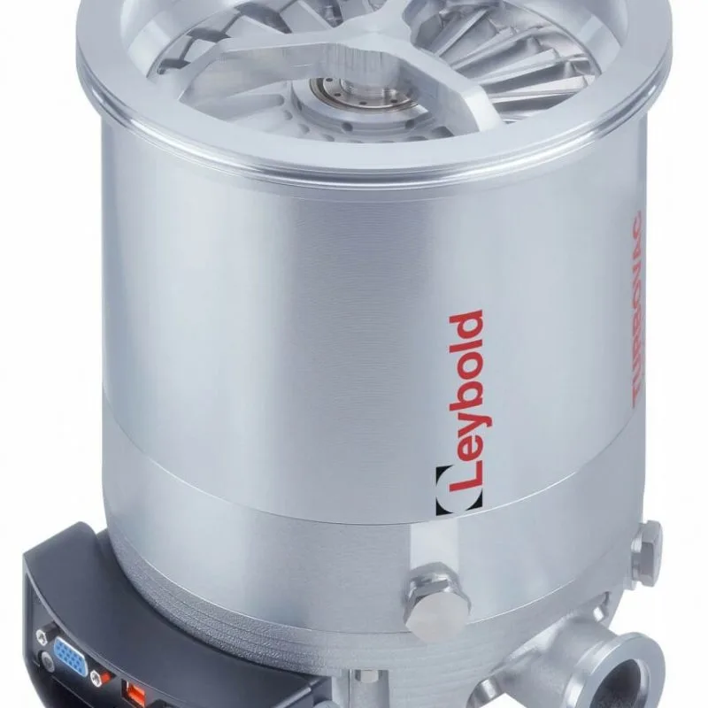
The Leybold TURBOVAC 90 i/iX offers 90 l/s nitrogen pumping speed with a DN63 ISO-K or CF inlet. A DN40 ISO-KF version of the 90 i is also available, rated at 38 l/s for nitrogen. Girovac can help you choose the inlet, controls and backing pump for your installation.
Part of the Leybold TURBOVAC i / iX turbomolecular pumps family. Compare the range and other model options.
Tell us the configuration and quantity you need. Include your process requirements if you would like help with selection.
View quote listThe Leybold TURBOVAC 90 i/iX offers 90 l/s nitrogen pumping speed with a DN63 ISO-K or CF inlet. A DN40 ISO-KF version of the 90 i is also available, rated at 38 l/s for nitrogen. Girovac can help you choose the inlet, controls and backing pump for your installation.
The TURBOVAC i/iX family is used in analytical instruments, surface analysis, research vacuum systems and coating equipment. Choose the pump for your gas load, target pressure and chamber connection. The DN63 connection makes the 90 a useful starting point when comparing pumps for smaller instrument connections. For process gases, include the gas composition and expected throughput in your enquiry.
The main table applies to the DN63 version. The DN40 version’s pumping speeds are listed separately below.
| Gas | Pumping speed (l/s) | Gas throughput (mbar·l/s) | Compression ratio |
|---|---|---|---|
| Nitrogen (N₂) | 90 | 10 | 1 × 10¹¹ |
| Argon (Ar) | 83 | 3 | 1 × 10¹¹ |
| Helium (He) | 90 | 11 | 1 × 10⁸ |
| Hydrogen (H₂) | 78 | 11 | 5 × 10⁷ |
Pumping speed describes the volume moved at the pump inlet; throughput also accounts for pressure. Compression describes the pressure ratio between the exhaust and inlet for a particular gas. These figures describe different aspects of performance and should be considered together. For argon and other heavy gases, the cooling and permitted gas load need particular attention.
| Gas | 90 i with DN40 inlet (l/s) | 90 i/iX with DN63 inlet (l/s) |
|---|---|---|
| Nitrogen (N₂) | 38 | 90 |
| Argon (Ar) | 36 | 83 |
| Helium (He) | 39 | 90 |
| Hydrogen (H₂) | 31 | 78 |
The DN40 inlet option is a TURBOVAC 90 i configuration. Use the inlet size and full part number when requesting a replacement.
| Specification | Value |
|---|---|
| High-vacuum inlet | DN63 ISO-K or CF; DN40 ISO-KF option on 90 i |
| Backing connection | DN16 KF |
| Ultimate pressure¹ | <8 × 10⁻⁸ mbar (ISO-K); <5 × 10⁻¹⁰ mbar (CF) |
| Maximum nitrogen forevacuum pressure | 14 mbar |
| Nominal operating speed | 72,000 rpm |
| Supply voltage | 24/48 V DC ±10% |
| Maximum power consumption | 240 W |
| Cooling | Convection; forced-air or water cooling as required by gas load and ambient conditions |
| Power at ultimate pressure, approximate | 9.5 W |
| Run-up time, approximate | 2 minutes |
| Operating ambient temperature | +5 to +45 °C, subject to cooling requirements |
| Protection rating | IP40 |
¹ Ultimate pressure is stated with a two-stage oil-sealed rotary vane backing pump. The pressure in your chamber also depends on leaks, outgassing, connecting pipework and process load. Maximum forevacuum pressure is an operating limit; the backing pump must keep below it at your intended throughput.
Mounting weight, ISO-K / CF: 3.1 / 4.8 kg for the i version; 3.6 / 5.3 kg for iX. These weights refer to the DN63 configurations. Use the dimensional drawing for the selected flange and cooling arrangement when allowing space for installation and service access.
Both versions have integrated drive electronics. The iX adds vacuum-system control, including a gauge-head connection and configurable accessory outputs. USB and digital I/O are available, while serial and fieldbus connections depend on the ordered interface and pump generation. Confirm the full pump part number and fitted front end when replacing or integrating equipment.
EtherNet/IP and EtherCAT: these are optional pump communication interfaces. Select the matching Anybus-capable configuration and module; an i/iX name alone does not identify the fitted protocol. Module installation, control priority and PLC configuration must follow the relevant pump and interface instructions.
TURBO.CONTROL i: the optional controller operates one TURBOVAC i/iX at a time via RS485 or USB and supports up to two compatible vacuum gauges. It provides a local display, operating-data logging and Ethernet access to its web server. That Ethernet web connection serves a different function from an EtherNet/IP or EtherCAT module on the pump. The tabletop housing, controller supply, gauges and communication cables must be specified as required.
On the standard i arrangement described in the March 2026 manual, accessories share the X201 output; two devices on a Y-cable switch together. The iX arrangement provides three accessory connections. A factory-assigned connection for a fan, relay or vent valve does not mean the accessory is included. Check the output load limits and configuration for the exact version.
A compatible pump power supply, mains/DC cables and backing pump are needed to run the system. These are separate from the controller’s own supply. Girovac can identify the required combination and which existing items can be retained.
The following manufacturer-listed options help specify a complete installation. They are quoted separately unless explicitly included in the selected package. Match the full pump part number, flange, supply and operating conditions before ordering.
| Option | Selection for this model |
|---|---|
| EtherNet/IP / EtherCAT | 410300V0906 / 410300V0907; requires the matching Anybus-capable pump configuration |
| Air cooling | Radial 800136V0007; axial 800136V0008 |
| Water cooling | 800135V0005 (6 × 1 mm hose) or 800135V0006 (¼-inch hose) |
| Power supply | TURBO.POWER integra 800100V0003; select mounting and cables for the pump |
| UK mains cable | 3 m 800102V0003 for TURBO.POWER integra |
| Backing-pump switching | Relay Box 800110V0030; check load and pump-output configuration |
| CF flange heating | DN63 CF, 230 V: 800137V0003; stainless-steel CF version only, with water cooling |
For pump-mounted TURBO.POWER integra on the 90/250, the range brochure lists mounting kit 800100V0005. Specify this separately from the power supply and confirm the mounting arrangement for the selected pump. The supplied short pump-to-power-supply cable and the UK mains cable serve different connections.
Relay Box: a configured 24 V DC pump output can switch a suitable mains-powered backing pump through this accessory. Its brief instructions state limits of 250 V AC, 10 A and 1.2 kW; all applicable limits and the starting load must be respected. It is not a universal motor starter. The listed kit includes a 2 m M8 control cable; mains leads are separate.
Venting and purge: a standard vent valve, power-failure vent valve and purge-gas arrangement perform different functions. Specify the intended shutdown behaviour, gas and process conditions. Cooling, venting and purge connections should be checked together with the available accessory outputs.
Flange bakeout: the heater instructions apply to stainless-steel CF flanges, require the pump’s water cooling to operate, and limit the heater temperature to 100 °C. Follow the pump’s own thermal limits and installation instructions; the heater temperature is not a blanket bakeout rating for the entire vacuum assembly.
The March 2026 manual is provided here for current interface and accessory selection. The dated performance references and curves elsewhere on this page remain identified with their original sources. Use the instructions matching the supplied pump variant.
For an integration quotation, include the full pump part number, PLC protocol, required gauge inputs, cooling method, venting sequence, backing-pump electrical rating and UK or other mains supply. A nameplate photograph helps confirm the appropriate interfaces and accessories.
Match the backing pump to both the gas throughput and the turbo pump’s forevacuum limit. Two-stage rotary vane pumps are one option; Dry backing pumps, including ECODRY and SCROLLVAC, may be appropriate where the process calls for them. We can help you compare the complete combination.
Convection cooling is suitable only within the permitted thermal operating conditions. Forced-air or water cooling may be required as gas throughput or ambient temperature rises. The manual specifies cooling water at 15–35 °C, with 30–60 l/h flow and 3–6 bar(g) pressure when water cooling is used. Keep access to the cooling connections in mind when planning the mounting.
Select vacuum gauges for the chamber and backing line separately: each needs the right measurement range, gas compatibility and control output.
Find your process gas in the legend, locate the inlet pressure on the horizontal axis, then read the pumping speed on the vertical axis. Pressure is plotted on a logarithmic scale. The speed available at your chamber will also depend on the connecting pipework.
This curve shows the DN63 version; use the separate table above for DN40 pumping-speed ratings.
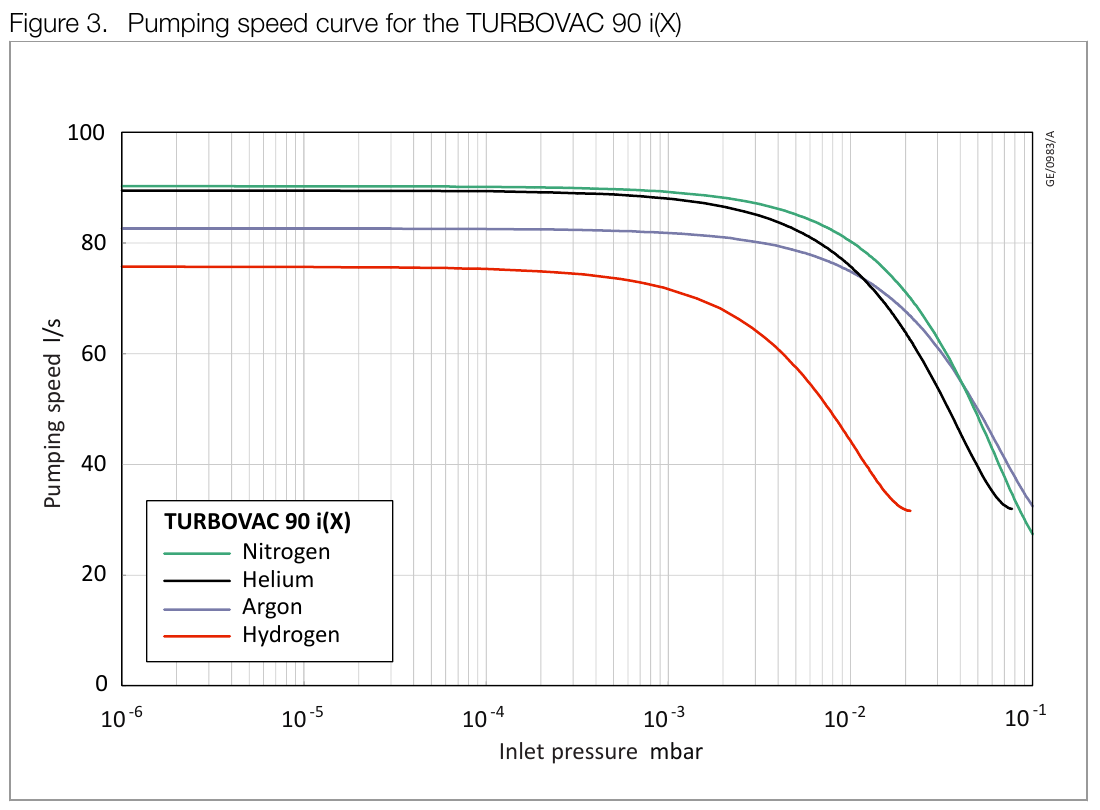
The curve must be used alongside the permitted backing pressure, gas throughput and cooling conditions. It shows pumping performance rather than electrical consumption; the power figures are listed separately above.
TURBOVAC i/iX pumps combine a turbomolecular rotor with hybrid bearing technology: a permanent magnetic bearing at the high-vacuum end and a lubricated mechanical bearing at the forevacuum end. The design does not use an oil reservoir in the pumping chamber. Cleanliness still depends on the complete installation, including the backing pump, seals and process gases.
Compare the TURBOVAC 250 i/iX if you need a DN100 inlet and 225 l/s nitrogen pumping speed. Check the gas-specific figures and installation requirements for both pumps before choosing.
No. It needs a suitable backing pump and the manufacturer’s start-up and shutdown sequence. If you already have a backing pump, send us its model and your process details so we can check whether it is suitable.
The chamber and backing line operate at different pressures. Choose vacuum gauges that cover each measurement range and work with your gases and controls. Tell us your target pressure and whether you need a local display or a signal for the control system.
Your quotation will set out the pump version, power supply, controls, cables and cooling accessories included. Let us know which items you already have so we can quote what you need.
Tell us the gas you are pumping, your target pressure, expected gas load and chamber connection. Request a quotation or call 01692 660117 for help with selection, price and availability.
Compare all turbomolecular pumps.
For a preassembled station with controls and a choice of backing arrangement, see the Leybold TURBOLAB 90 pumping station. Compare bench and cart configurations, inlet flanges and dry or oil-sealed backing options.
For a dry bench station with local control and DIVAC or SCROLLVAC backing, see the Leybold TURBOLAB Core 90. Compare backing capacity, inlet flange, measurement and supply options for your application.
| Manufacturer | LEYBOLD |
|---|---|
| Equipment type | Turbomolecular Pumps |
| Pumping speed — nitrogen | 90 l/s (DN63); 38 l/s (90 i DN40) |
| End / ultimate pressure | <8 × 10^-8 / <5 × 10^-10 mbar, with two-stage oil-sealed rotary vane backing pump — ISO-K / CF |
| High-vacuum inlet connection | DN63 ISO-K or CF; DN40 ISO-KF on 90 i |
| Backing connection | DN16 KF |
| Maximum power consumption | 240 W |
| Cooling | Convection; optional air or water cooling |
| Pumping speed — argon | 83 l/s (DN63); 36 l/s (90 i DN40) |
| Pumping speed — helium | 90 l/s (DN63); 39 l/s (90 i DN40) |
| Pumping speed — hydrogen | 78 l/s (DN63); 31 l/s (90 i DN40) |
| Gas throughput (N₂) | 10 mbar·l/s |
| Compression ratio (N₂) | 1 × 10¹¹ |
| Gas throughput (Ar) | 3 mbar·l/s |
| Compression ratio (Ar) | 1 × 10¹¹ |
| Gas throughput (He) | 11 mbar·l/s |
| Compression ratio (He) | 1 × 10⁸ |
| Gas throughput (H₂) | 11 mbar·l/s |
| Compression ratio (H₂) | 5 × 10⁷ |
| Maximum forevacuum pressure (N₂) | 14 mbar |
| Operating speed | 72,000 rpm |
| Supply voltage | 24/48 V DC ±10% |
| Power at ultimate pressure | Approximately 9.5 W |
Send the pump model and part number when asking about a replacement. Compatibility depends on the equipment and operating conditions.
Confirm the exact version, electrical supply and connections. Ask whether oil, filters, fittings, cables or controllers are included or separately specified.
Availability, lead time and the applicable warranty are confirmed for your quotation. A catalogue listing does not reserve stock.
What to check in your quotation · Delivery · Returns and faults
Leybold TURBOVAC 90 i/iX Turbomolecular Vacuum Pump
Prefer to talk? 01692 660 117 · [email protected]
We use your details to respond to your enquiry. Read our privacy policy.
EDWARDS
LEYBOLD
EDWARDS
LEYBOLD
Compare the stated conditions as well as the values. A missing specification is not a zero rating; confirm suitability with Girovac.
Copyright © 2026 Girovac Ltd | Registered in England and Wales Number: 01758137 | Cookie Policy | Privacy Policy | Delivered by Postino