

A vacuum pump’s pumping speed tells you the volume of gas it can move at its inlet per unit time. Its ultimate pressure tells you the lowest pressure it can achieve under specified test conditions. You need both figures when choosing a pump, but neither tells you exactly how it will perform on your chamber.
Two pumps can reach a similar ultimate pressure yet take different lengths of time to evacuate the same vessel. A pump with a high pumping speed may also be unsuitable if it cannot reach the pressure your process requires.
Reading the figures
Pumping speed is usually given in litres per second (l/s) or cubic metres per hour (m³/h). One litre per second equals 3.6 m³/h. To convert m³/h to l/s, divide by 3.6.
The quoted speed needs context. A pump does not necessarily maintain that speed throughout its pressure range. Check the pumping-speed curve at the pressure where your process will run, along with the gas and operating conditions used for the measurement.
Ultimate pressure is usually stated in mbar, Pa or Torr. A lower absolute pressure means a deeper vacuum. This figure describes performance under the manufacturer’s stated conditions. The pressure reached in a connected chamber also depends on its seals, pipework, internal surfaces and process gas load.
Why the connection matters
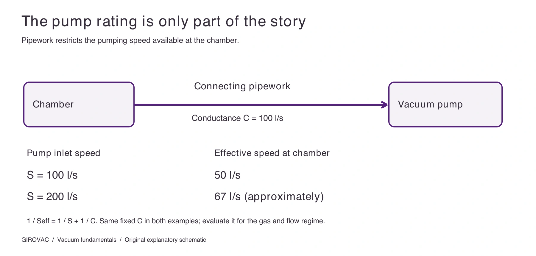
Gas has to travel from the chamber to the pump. Pipework, valves, filters and traps introduce resistance to that movement. The resulting speed at the chamber is called the effective pumping speed. It can be substantially lower than the speed available at the pump inlet.
Consider a simplified example in molecular flow. A pump provides 100 l/s for a particular gas, and its connecting line has a conductance of 100 l/s for the same gas and temperature. Using effective speed = (pump speed × conductance) ÷ (pump speed + conductance), the speed at the chamber is 50 l/s.
Fit a 200 l/s pump to the same line and the effective speed rises to about 67 l/s. Doubling the pump size has increased the speed at the chamber by only a third. These are illustrative figures, assuming steady molecular flow, no additional gas sources in the line and no other restrictions. The pipework guide examines this in more detail.
The chamber also contributes gas
Evacuation involves more than removing the air initially inside a vessel. Moisture and other gases can leave internal surfaces through outgassing. Leaks may admit gas, and the process itself may release vapour or introduce a continuous flow.
At a steady operating point, where the pump’s own limiting pressure is negligible, chamber pressure is approximately the gas load divided by the effective pumping speed. More incoming gas means a higher pressure unless the system can remove it quickly enough.
An empty, clean chamber can therefore behave differently from the same chamber containing a wet sample or running a process.
Examples from pump specifications
Nominal capacity is not the whole performance curve
Read the label used by the manufacturer. Nominal flow, PNEUROP pumping speed and pumping speed at a particular pressure can be different figures for the same model.
The MIL’S EVISA E100.R datasheet gives a useful example at 50 Hz: 100 m³/h nominal flow, 96 m³/h PNEUROP pumping speed and 52 m³/h at 1 mbar inlet pressure for the HV version. The PNEUROP measurements are stated at 20°C. Selecting from the 100 m³/h figure alone would miss the performance at the working pressure.
Compare pumping speed for the right gas
For a turbomolecular pump, the gas species matters. The Leybold TURBOVAC 250 i/iX manual lists 225 l/s for nitrogen, 250 l/s for helium and 210 l/s for both argon and hydrogen. The model number is not a universal speed rating.
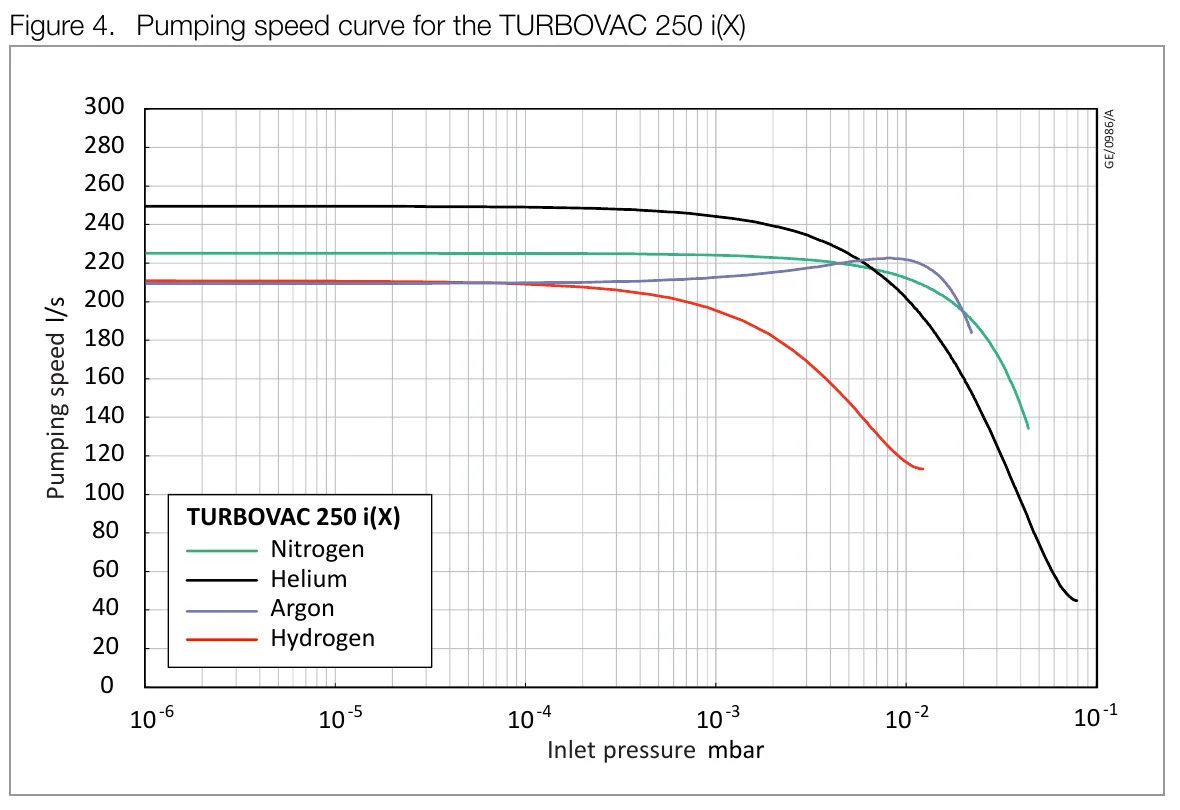
Choose the curve for the process gas, find the intended inlet pressure, and read the corresponding pumping speed. The shape of the curve depends on the pump and gas; do not assume every technology follows the same pattern. The TURBOVAC 250 i/iX listing explains its backing and cooling requirements.
Keep continuous duty separate from end vacuum
End vacuum is not necessarily the lowest pressure permitted for continuous use. The MIL’S SIRELLA SL300.R datasheet distinguishes 50 mbar end vacuum from 150 mbar continuous end vacuum at 50 and 60 Hz. Use the continuous-duty limit when assessing sustained operation.
What to compare before buying
Start with the pressure the process needs and how quickly it must reach it. Compare performance across the relevant pressure range, using the gas and electrical frequency you will actually operate with.
Give Girovac the chamber volume, target pressure, evacuation time, process gases and pipe dimensions. For a replacement, include the existing model and explain what you want to improve. A slow evacuation and difficulty maintaining pressure during a process can point to different requirements.
Send your requirements to Girovac, or use the equipment catalogue to compare suitable models and their stated conditions.
Technical reference: Leybold, Fundamentals of Vacuum Technology, 2016 edition, sections 1.1, 1.5 and 2.3. Leybold’s online vacuum fundamentals provides further reading.
MIL’S EVISA E100.R / E100.R HV datasheet (PDF), first page, printed page 26; Leybold TURBOVAC i/iX operating instructions (PDF), pages 19–22; and the SIRELLA SL300.R datasheet linked from its product page. Content revised September 2026 using these sources.
Updated September 2026. Model-specific settings and limits must be checked against the equipment’s operating instructions.